English
 Russian
 Spain
Spain
[email protected]
+86-13777149766
As shown in figure 1-5 is the cold chamber die casting mechanism drawing, it is composed of column frame, frame, press, hydraulic, electrical, lubrication, cooling, safety protection and other components. According to the function classification of machine parts and components, we divide the Cold Chamber Die Casting Machine into five categories: closing die, pressing, hydraulic transmission, electrical control and safety protection.
The following takes the MT300 Cold Chamber Die Casting Machine produced by YOMATO Machinery as an example for structural analysis.
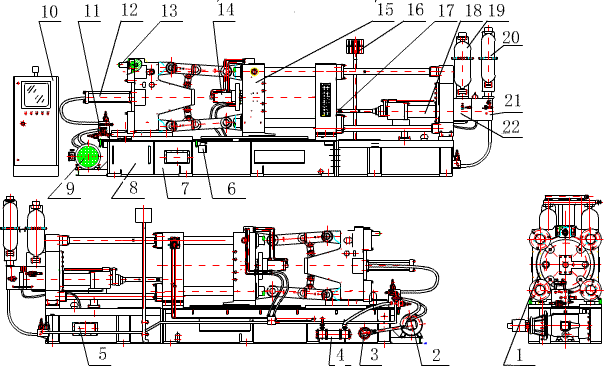
Fig .1-5 Die casting mechanism of cold chamber
1-- Mold adjustment Gear 2-- Hydraulic Pump 3-- Filter 4-- Cooler 5-- Injection Oil Tank 6-- Curved Elbow Lubricating Oil Pump 7-- Main Tank 8-- Frame 9-- Electric motor 10-- Electric box 11-- Mold close oil circuit board assembly 12--Mold close hydraulic cylinder 13-- Mold adjustment hydraulic motor 14-- Ejection hydraulic cylinder 15-- Movable mold platen 16-- Mold cooling water observation window 17-- Plunger head 18-- Injection hydraulic cylinder 19-- First injection accumulator 20-- Intense accumulator 21-- Intense circuit board assembly 22-- Injection circuit board assembly
(1) Modelling mechanism
The die-closing mechanism mainly plays the role of realizing the closing, opening and locking of the mould and ejection of the product. It is mainly composed of shaped seat plate, moving seat plate, pull bar (Corinne column), elbow bending mechanism, ejection mechanism, mold adjusting mechanism and so on.
1. characteristics of hydraulic double-curved elbow die mechanism
(1) By means of the elbow connecting rod system, the thrust force of the combined hydraulic cylinder can be enlarged by 16~26 times. Compared with the hydraulic combined device, the consumption of high pressure oil decreases, the diameter of the combined hydraulic cylinder decreases, and the power of the pump decreases accordingly.
(2) The moving speed of the closing and opening die is variable speed. During the closing motion, the moving speed of the moving seat plate is gradually slowed down after rising from zero to the maximum value. As the elbow rod is gradually straightened to the end, the closing speed is zero and the mechanism enters the state of self-locking (locking state). In the process of opening, the moving plate moves from slow to fast, and then from fast to zero, which is very suitable for the whole motion design of the machine.
(3) When the die-casting die is tight and the elbow rod is straight into a straight line, the mechanism is in the state of self-locking, at this time, the thrust of the die-closing hydraulic cylinder can be removed, and the die-closing system will still be in the state of closing.
(4) The three elements of the motion of the closing die are as follows: the closing force: the locking force formed by the template to the die when the closing die is terminated.
mode locking force: the final locking force formed by the template on the mold when the alloy liquid is injected into the mold cavity during the die closing termination. deformation force: internal force of the mechanism due to deformation during the locking die.
Mould-shifting force: the force applied to the moving plate when the die is closed.
Expansion force: the force that causes the mold to separate due to the pressure of the alloy cavity.
Die-shifting speed: the speed of the motion of the moving plate and the moving die in the closed open die motion. the mode shifting velocity is a variable speed process. The speed of movement should be a slow-fast-slow process of change. This can not only make the mold run safely, the casting can be pushed out smoothly, but also increase the number of cycles of the machine.
2. ejection hydraulic cylinder assembly
The ejection hydraulic cylinder is also called the thimble hydraulic cylinder, and the ejection hydraulic cylinder assembly is based on the pressure of the liquid to drive the push rod (thimble) movement so that the casting is ejected from the die casting die. At present, the commonly used hydraulic ejection mechanism, its jacking force, ejection speed and time can be adjusted by hydraulic system.
3. Modulation Mechanism
die casting machine in the design process, need to set mold adjustment mechanism to adapt to a certain range of die casting die, in the machine technical parameters, should determine the maximum die thickness size Hmax and the minimum die thickness size Hmin as the machine user selected die casting die parameters. This adjustment of the maximum and minimum die thickness is achieved through the mold adjustment mechanism. The mode adjusting mechanism is to drive the transmission mechanism with the hydraulic motor or the mode adjusting motor, so that the tail plate and the moving seat plate of the mould locking column frame move axially along the drawing bar, thus achieving the purpose of increasing or reducing the spacing between the moving and setting seat plates.
4. elbow lubrication system
Elbow is a very important moving component of die casting machine. In order to reduce the wear of its moving pair, it is necessary to maintain a properly clean lubricating oil film on the surface of the moving pair, and excessive oil supply is as harmful as insufficient oil supply, which will produce additional heat, pollution and waste.A centralized lubrication system is used to lubricate the elbow part of die casting machine produced by YOMATO Machinery Factory Co. Ltd. The so-called centralized lubrication system is a lubricating oil with a certain displacement and pressure provided by one oil pump (mainframe for two oil pumps), which supplies oil to all the distributors on the main and secondary oil routes in the system, while the distributor distributes the oil to each lubricating point according to the required oil quantity; at the same time, the controller completes the functions of lubrication time, frequency, fault alarm, shutdown and so on, in order to achieve the purpose of automatic lubrication. Cold chamber die-casting machine elbow lubrication generally choose the pressure lubrication pump, it has the following characteristics:
1) the pressure output mode is adjustable output structure, meet the needs of various machines, can make relative pressure matching adjustment.
An oil level detector is attached to the 2) to measure the stock of oil supply in the storage tank, timely response return, and connect the strain action.
3) the immediate need for a keystroke device, the machine at the beginning of use, immediately get the amount of oil due, reduce unnecessary friction.
4) deep into the bottom of the oil absorption, so that the oil power greatly increased, and can clear the lack of air spacing in the tubing.
The 5) is equipped with an oil pressure detection device (1~0.3 MPa) to detect the following leakage:
The failure of the pipeline can be detected by insufficient pressure in the pipe.
Obstruction of oil intake can be detected by oil turbidity.
The motor is not working properly.
When the parts are aged and the output power is poor, the pressure is insufficient.
The lack of oil can be detected in the oil barrel.
(ii) Injection mechanism and working principle
The pressing mechanism is the mechanism of pressing metal into die cavity for filling forming. It is mainly composed of hydraulic cylinder assembly, pressure chamber
the structural properties of (feed cylinder), punch (hammer head) assembly, fast-Injection accumulator assembly, and supercharged accumulator assembly play a decisive role in casting pressure, die-casting speed, supercharged pressure and time during die casting, and directly affect the profile size, mechanical properties, surface quality and compactness of castings. The following is an example of the MT300 Cold Chamber Die Casting Machine produced by YOMATO Machinery
The hydraulic oil of the system enters the C2 cavity through the oil circuit assembly plate and then enters the C1 cavity through the A3 channel to push the pressure ejection piston 2 to the left when the pressure ejection is started, so as to realize the first stage slow pressure ejection motion. when the Injection head 1 crosses the gate of the Injection chamber (barrel), the control oil valve of the hydraulic accumulator 3 opens, so that the hydraulic oil of the lower cavity of the accumulator 3 enters the C1 cavity quickly through the A1、A3 channel. the oil quantity of the hydraulic oil in the C1 cavity increases rapidly, which makes the speed of the Injection piston move faster and realizes the second stage fast Injection motion. the pressure ejector fills the alloy fluid into the mold cavity. when the filling is about to terminate, the alloy fluid is solidification. at this time, the resistance of the pressure ejector forward increases. this resistance will feed back to the control system. the control oil valve of hydraulic accumulator 4 opens and the hydraulic oil in its lower cavity enters the C3 cavity quickly through the A2 channel, thus pushing the pressurized piston 5 and piston rod 6 to move quickly to the left. When the piston rod 6 and the floating piston 7 inside and outside cone surface are joined A3 the channel is truncated, so that the C1 forms a closed cavity. The push of the pressurized piston 5, the piston rod 6, the floating piston 7 and the hydraulic pressure of the C1、C2 cavity together make the piston 2 obtain a supercharging effect. When opening the mold, the system hydraulic oil enters the C4 cavity, pushing the piston 2 to move right C1 the hydraulic oil in the cavity pushes the piston rod 6 to move right, thus opening the channel A3,C1 the hydraulic oil in the cavity is returned to the tank through the integrated oil plate through the A3、C2. Hydraulic oil of the C3 cavity is driven by the piston 5 to return to the tank through the integrated oil circuit board, and the piston 2 continues to move right until the piston rod 6 returns to its initial position.
In the whole process of pressing and firing, the speed and time of slow, fast and supercharging can be adjusted by the control oil valve installed on the oil circuit integrated board.
Fig .1-6 Schematic diagram of compression

|
1-- Plunger head 2-- Piston 3--4-- Accumulator 5-- Intense Piston 6-- Piston Rod 7-- Floating Piston 8-- Sleeve
C1、C2 Injection Chamber C3 Intense chamber C4 Return Chamber
A1、A2、A3 Channel
(iii) Hydraulic transmission system
Hydraulic transmission system is a system that transmits power through various hydraulic components and circuits, thus realizing various action programs. The hydraulic transmission system consists of the following five basic parts:
Hydraulic pump ,1) power element, which supplies pressure oil to the hydraulic system, is a device that converts the mechanical energy output from the motor into the hydraulic energy of the oil.
A 2) actuator - a hydraulic cylinder or a hydraulic motor - is a mechanical energy device that converts the hydraulic energy of an oil into a driving working component. The actuator for linear motion is called a hydraulic cylinder; the actuator for rotational motion is called a hydraulic motor.
3) control elements -- various control valves, such as directional control valve, pressure control valve, flow control valve, etc., are used to control and regulate the flow direction, pressure and flow rate of oil in hydraulic system to meet the requirements of the movement of the actuator.
4) auxiliary elements - including fuel tanks, filters, accumulators, heat exchangers, pressure gauges, fittings and sealing devices, etc.
5) working medium - hydraulic oil through which energy is converted, transferred and controlled.
The hydraulic system of die casting machine is mainly composed of hydraulic pump, closed open die hydraulic cylinder, ejection hydraulic cylinder, Injection hydraulic cylinder, adjusting die hydraulic motor, hydraulic control element, hydraulic accumulator, filter, air filter, heat exchanger.
1. hydraulic accumulator
The purpose of the hydraulic accumulator is to hold a liquid quantity at liquid pressure and give it when needed. Reasonable selection of hydraulic accumulators has an extremely important effect on the economy, safety and reliability of hydraulic system.
Piston accumulator is mainly suitable for large volume and large flow system, which can be used between low temperature-53℃ and high temperature 121℃, and its strength and reliability are high. the gas (usually nitrogen) and liquid of the piston type accumulator are separated by a freely moving piston that moves in a hydraulic cylinder liner and seals the gas and liquid through a sealing ring. the maximum pressurization ratio (i.e. the ratio of gas pressure to working pressure) is 1:10. The friction loss and leakage of piston should be taken into account in the selection, so it is not suitable for the system circuit with high working frequency and low pressure difference.
The nitrogen and liquid in the airbag accumulator are separated by the sealed elastic capsule, the nitrogen is packed in the capsule, and the capsule is packed in the steel container so that the preloaded gas can not leak out. Its work features sensitive induction, rapid, low running inertia.
The working principle of airbag accumulator: when filling liquid, the hydraulic oil of hydraulic system pushes the opening valve into the steel vessel and compresses the nitrogen gas in the skin sac to a certain volume; when releasing liquid, the hydraulic oil flows out from the disc valve mouth into the required vessel, and the nitrogen pressure in the airbag acts as the driving force for the hydraulic oil and the pressure tightening disc valve. The disc valve can restrict the air bag from being pressed out of the hole.
The cold chamber die-casting machine uses the hydraulic accumulator to replenish the hydraulic oil of the pressing mechanism in time to increase the pressure and speed of the pressing motion.
2. filters
The purpose of the filter is to filter out impurities in the oil, reduce the pollution of the pressure medium to the allowable level, and ensure the normal operation of the hydraulic system. The accuracy of the filter can be divided into four categories: coarse filter, which can filter out impurities d≥0.1 mm in diameter, and ordinary filter, which can filter out
d=0.1~0.01 mm impurities; fine filter - can filter out the diameter of 0.01~0.005 mm impurities; special fine filter - can filter out the diameter of 0.005 mm~0.0001 impurities. Common filters are mesh type, wire gap type, paper core type, sintering type several, die casting machine often use mesh type filter.
3. air filter
The air filter is generally installed on the upper cover of the main tank, which has two functions: one is as an oil injection filter, which can prevent impurities from entering the tank when adding hydraulic oil; the other is as a ventilation filter, the fluctuation of the liquid level of the tank requires air to balance during the operation of the system, which can filter the air flowing into the tank through the filter.
4. fuel tank
The tank is used in the hydraulic system to store the oil to ensure the adequate supply of the working medium of the hydraulic system, but also has the function of heat dissipation, the escape of the air that seeps into the oil and the precipitation of the dirt in the oil. There are two types of oil tank: integral type and separation type. The integral type refers to the use of the base of the main engine and so on as the fuel tank, while the separated fuel tank is separated from the main engine and forms an independent oil supply unit with the pump and so on. Usually the fuel tank is welded with 2.5~5 mm steel plate, as shown in Fig .1-11 as a small separate tank.
5. heat exchanger
The working temperature of commonly used oil in hydraulic system is 40~50℃, generally the highest is not higher than 55℃, and the lowest is not less than 15℃. Too high temperature will make the oil quickly deteriorate, at the same time, the volume efficiency of the hydraulic pump will decrease; too low temperature will make the hydraulic pump difficult to absorb oil. In order to control the oil temperature, the tank is often equipped with coolers and heaters, heat exchangers are the general name of coolers and heaters.
(1) Cooler coolers can be divided into air-cooled, water-cooled and ammonia-cooled forms. Water-cooled coolers are mainly used in hydraulic systems of die-casting machines, which are generally installed in return oil circuits to avoid high pressure.
(2) The methods of oil heating in heater hydraulic system include hot water or steam and electric heating. Because the electric heater is easy to use and easy to control the temperature automatically, it is widely used.
(iv) Electrical control system
The electrical control system gives power to the machine and ensures that the machine operates at predetermined pressures, speeds, temperatures and times.
be composed of electric motors, PLC control systems and various electrical components and electrical wiring, see Section 6 of this chapter for details.
(5) Safety protection devices
1. protection of the pressure zone
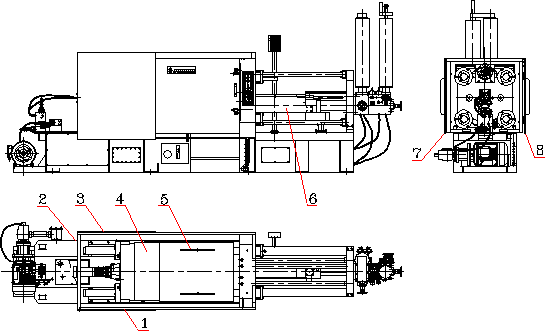
The front safety door 8, the rear safety door 7, the movable seat plate cover 5 and the flying material baffle 6 are installed in the pressing area to prevent the danger of metal spatter during the ejection.
2. Protection in Molding Movement Area
Front safety door 8, rear safety door 7, movable seat plate cover 5, tail plate cover as shown in Fig .1-13 are installed around the movement area of the die closing
4. hinged rear cover plate 3, hinged front cover plate 1, hinged tail cover plate 2 to prevent accidental injury when elbow (machine hinge), template thimble is moving.
|
Fig .1-7 Protective Equipment of Cold Chamber Die Casting Machine
1-- front fixed cover 2-- rear cover 3-- back fixed cover 4-- Tail cover 5-- Movable platen cover 6-- Flying material protect cover 7-- Rear safety door 8-- Front safety door
3. security control system
(1) The front door safety control system The front door safety control system is detected by the limit switch (Ji) limit bar (Ji)(or glue edge sensor) and controlled by the PLC control system, and its safety control schematic diagram is shown in Figure 1-8.
1) the current safety door automatically closes, if the foreign body (such as hand, etc.) is clamped, then the limit bar is pushed, the limit switch inputs the action signal into the computer, the computer sends out the signal, so that the front safety door opens automatically, and the mode-locking action can not be carried out.
2) the safety door is closed, if the closing is not in place, there are two limit switches to transmit the signal to the computer, then the computer sends out the signal, the machine can not do the open-lock mode movement.
3) the closing door is not in place, when the limit switch does not operate, the hydraulic safety valve can not be electrified, and the hydraulic control valve does not operate, resulting in the mode locking action can not be carried out.

Fig .1-8 Schematic diagram of safety control system of die casting machine in cold chamber
(2) The rear safety door control system rear safety door is controlled by two limit switches. When the door is not in place, the limit switch acts, cutting off the control circuit, and the machine can not act, so that the mode-locking action can not be carried out.
4. Emergency Protection
Cold chamber die-casting machine is generally set with 3~5 emergency stop buttons, respectively set on the main electric box, machine front operation panel, starting plate, setting seat plate, small electric box of ejection material. During the operation of the machine, press any emergency stop button, the motor will stop running, and have emergency stop display and alarm.
.jpg)
Contact: Sean Jiang
Phone: +86-13777149766
E-mail: [email protected]
Whatsapp:8613777149766
Add: No.6,Wenjing Road,Jintan Economic Development Zone,Changzhou,Jiangsu,China
We chat